Introduction to the structure of carbide wire drawing dies
Wire drawing dies are molds used for drawing metal wires or optical fibers. The metal is pulled through the die, reducing its size and shaping it into wires of various […]
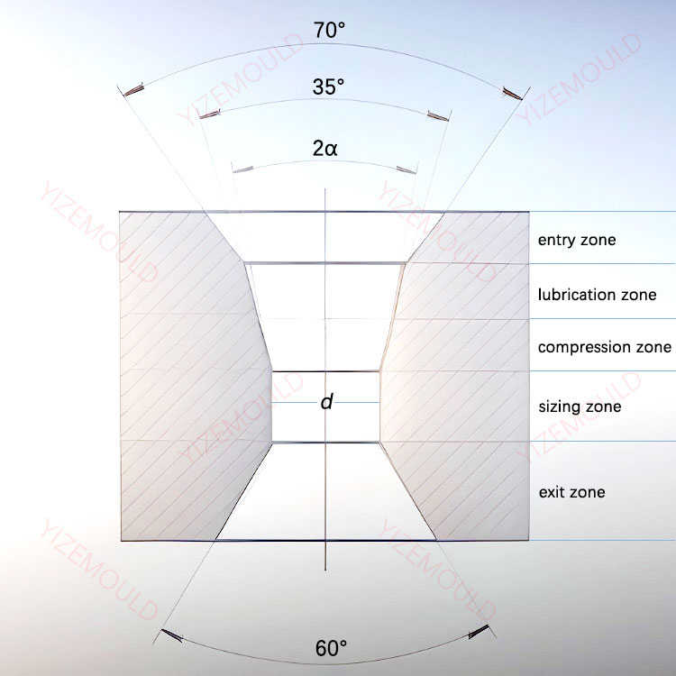
Wire drawing dies are molds used for drawing metal wires or optical fibers. The metal is pulled through the die, reducing its size and shaping it into wires of various diameters. When the diameter of the metal wire is large, a conical die is usually used, while an arc-shaped die can be used for smaller wire diameters. The die hole of a conical die is generally divided into five regions, as shown in the diagram. The functions and shapes of each region are as follows:
Our factory business: carbide parts, mold parts, medical injection molds, precision injection molds, teflon PFA injection molding, PFA tube fittings. email: [email protected],whatsapp:+8613302615729.
- Entry zone: The angle of the entry zone is an important parameter for wire drawing dies. It ensures that the contact point of the wire entering the die occurs at the same height position within the compression zone of the die and facilitates the entry of the wire. The entry zone provides a smooth shape for the wire to pass into the lubrication zone and the compression zone, allowing the lubricant to reach the working surface of the die.
- Lubrication zone: The lubrication zone delivers the lubricant to the working area. The length and taper angle of the lubrication zone vary depending on the type of lubricant and the wire diameter. When the lubricant is a viscous liquid, a larger taper angle should be chosen for the lubrication zone to ensure smooth entry of the lubricant into the compression zone and prevent wedge-shaped blockage. However, if the taper angle of the lubrication zone is too large, it will be difficult to generate a fluid pressure effect, which affects lubrication effectiveness.
- Compression zone: The compression zone is where the wire undergoes plastic deformation and obtains the desired shape and size. There are two shapes for the compression zone: conical and arc-shaped. The main dimensional parameter for the conical compression zone is the compression angle α. The size of α angle, along with the pressure applied to the inner hole of the die and its distribution pattern, and the mechanical properties of the drawn wire, plays a decisive role. If α angle is too small, the contact area between the billet and the die wall increases, leading to increased frictional resistance. If α angle is too large, the metal in the deformation zone undergoes sharp bending, resulting in increased additional shear deformation, which leads to increased drawing force and non-contact deformation. Therefore, there is an optimal range for α angle, within which the drawing force is minimized.
- Sizing zone: The purpose of the sizing zone is to ensure that the wire obtains a stable and precise shape and size. The diameter of the sizing zone is determined based on the allowable tolerance of the wire and the elastic deformation that occurs during the drawing process, while also considering the service life of the die. Typically, the sizing zone is selected with a negative tolerance size for the wire. When determining the length of the sizing zone, the following requirements should be met: sufficient wear resistance, energy consumption during drawing, and minimizing the possibility of wire breakage. If the sizing zone is too short, it can cause shaking of the wire during drawing and result in bamboo-like defects. It can also quickly wear out the inner hole of the die, leading to size deviations. If the sizing zone is too long, it increases energy consumption during drawing and reduces the lifespan of the die.
- Exit zone: The purpose of the exit zone is to prevent the metal from being scratched as it exits the die hole and to prevent the peeling of the rear edge of the sizing zone due to stress. The length of the exit zone is generally taken as (0.2~0.3)d, where d represents the wire diameter.